Custom dial VU images
A full-screen VU for the dial display is defined with an XML file and a couple of image files. I recommend storing all plugin-related files in the Documents/Trevliga Spel folder to keep them together. This ensures the profiles work on multiple computers, as the plugin automatically translates paths to that folder.
Images
Image | Description |
|---|---|
Background image | The background image is static and will always serve as the base layer. The image may be partially transparent if you want the dial strip background to be visible under the VU meter. The image should be in .png or .jpg format and fill the entire screen space at 200x100px. |
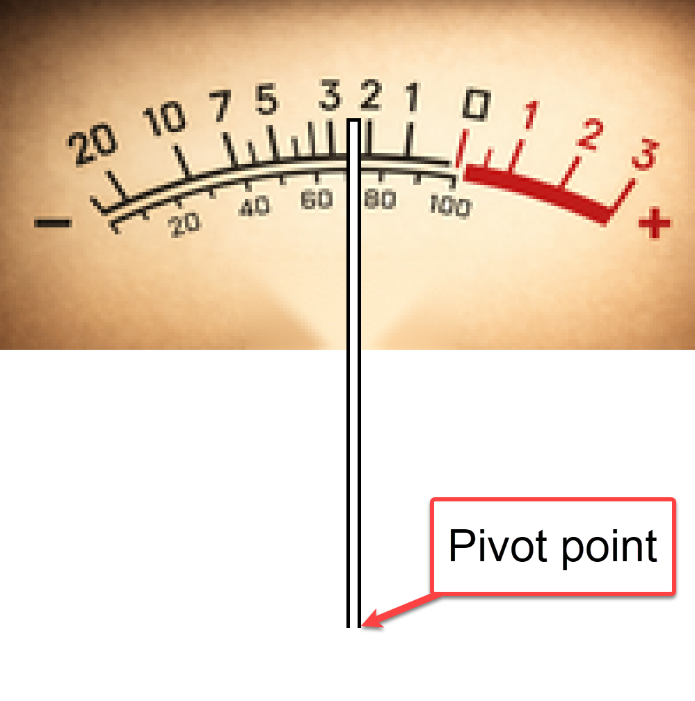
Needle image | The Needle image is the VU meter needle. The image should show the needle pointing straight up at the 12 o'clock position. The image can be .jpg or (preferably) .png, and it should be as close as possible to the image content; if the needle is 4 px wide, the image should be 4 px wide. The needle pivot point may be below the visible image, and the file should include the full height from the pivot point up to where the needle should end on the VU scale. |
Peak hold image | The Peak hold image shows the peak hold position. It is most likely a variation of the Needle image and shares the same image requirements (12 o'clock position, minimal width, and full height from the pivot point to the VU scale). The built-in VU designs use a simple red needle, but you can design the peak hold image as you like. |
Frame image | The Frame image is used to display a frame around the VU meter, and whether it is used is controlled by the "Show frame" checkbox in the editor. The image should cover the full screen size, 200x100px, and include a transparent area inside the frame. The image must be a .png file because it must have a transparent center so the VU meter can be displayed. |
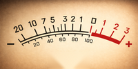
The images are rendered in the order described in the table above. All images should be transparent in areas that are not to be rendered in the image layer.
Configuration file
The configuration for a dial VU design is stored in an XML file, and if you want to use a specific design for a dial, you only need to reference that XML file.
- If you want to add a new design (one not previously referenced) to a dial, press the Add design button and select the XML file that defines the design. This will select the current dial's design and add its name to the dropdown list for easy access when configuring other dials.
- If you want to add the same design to other dials, simply select the design from the dropdown list.
File content:
<?xml version="1.0" encoding="utf-8" ?>
<VU displayname="Golden">
	<Background image="background.png" />
	<Frame image="frame.png" />
	<Needle image="needle.png"
		peakholdimage="peakhold.png"
		shadow="3,3,2,2,#ff000000"
		pivotpoint="100,178"
		minangle="-32"
		maxangle="32"/>
</VU>
Attribute | Description |
|---|---|
VU - displayname | This is the name that the design will have in the dropdown. You can set whatever name you like, preferably a name not already in the dropdown list.
|
Background - image | The file name for the background image. |
Frame - image | The file name for the frame image. |
Needle - image | The file name for the needle image. |
Needle - peakholdimage | The file name for the peakhold image. |
Needle - shadow | If you want a shadow to be displayed for the needle, this is where you define it. Format: "x, y, bx, by, color".
|
Needle - pivotpoint
| The pivot point is the needle base's coordinate; the needle rotates around it. In many cases, the pivot point will be outside the visible area, which is OK. The x-coordinate is most likely 100 (center of the area), while the y-coordinate can be well below the visible area. Many of the built VU designs have the coordinates (100, 178). |
Needle - minangle | These two properties define the minimum and maximum angles of the needle, with the 12 o'clock position set to 0. When fixed at the pivot point at the bottom and rotated to minangle, it should point to the lowest value on the VU meter, and when rotated to maxangle, it should point to the maximum value on the VU meter. |
XML tags and attribute names are case-sensitive. All images must be in the same folder as the XML file, and the images should be defined with the file name only (not the full path).